
By Phil Kreveld
As the renewables transition advances, a shortage of reactive power is in prospect. The capacity investment scheme, and Tim Nelson’s electricity services entry mechanism, replacing the CIS, do not address this shortage. It is left to transmission networks to provide this, although there is at times sharing of capital expenditure with generators, in particular for wind and solar connection approvals. Reactive power is not mentioned by name, but its effect, system strength is.
The capacity of any generator type is indicated by its MVA rating. This is composed of active power and reactive power as shown below:
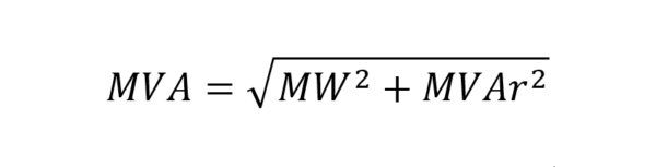
Megawatts (MW) is active power providing saleable energy.
MVAr megavolt-amps, reactive, is reactive power, not paid for. However, the MVA rating figures in the construction costs of generators. Apportioning between MW and MVAr is not a specific design parameter. MVA rating indicates the size for heat dissipation to be efficient.
The renewable equipment is largely provided by inverters, and the semiconductor switches limit the MVA rating to 1.1 per unit (longer time) to 2.0pu (very short time) of name plate rating. This compares with synchronous generators with 3 to 6 times name plate rating, and generally sufficient time to allow operation of circuit breakers.
If inverters have to provide reactive support with their typical over-current rating, using the above formula yields on a per unit (pu) basis.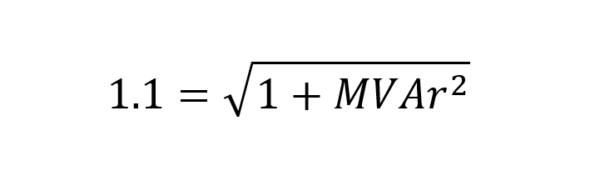
This shows 0.46pu as the maximum reactive component. However, continual 10% above rating operation is undesirable for the longevity of the generator. Therefore, reactive power provided by inverters is at the expense of active power and revenue. For example, if 0.46pu reactive support is required, then using the formula for MVA rating of 1.0pu above, yields an active power of 0.89pu, or 11% loss of active power (and revenue). A synchronous condenser at the inverter bus can provide the reactive power
and for some cases the cost is shared between the network and the generator owner.
System strength has the following requirements: maintenance of voltage at specific buses throughout the network within required high and low limits, and within the range of allowable maxima and minima of power, as well as maintenance of a pure sinewave shape. Increasingly longer transmission lines and replacement of synchronous machines capable of sourcing reactive power of the order of 0.6pu with inverters capable of 25% or less reactive support need overall system design oversight.
Reactive support for transmission lines reaching towards to ¼ wavelength, such as EnergyConnect or CopperString require very responsive reactive power control. The Australian Energy Market Operator mandates certain synchronous generation plant to absorb reactive power from transmission lines that are subject to unloading during high insolation causing close to energy independence, for example in South Australia. These generators then operate in under-excited mode, a less-than-ideal situation capable causing flame-out in boilers.
Reactive power results from the requirements of transmission lines, rather than the demands from centres of energy consumption, their power factors approaching unity. A transmission line is defined by it surge impedance limit in megawatts. If such line has a load that is more than its safety integrity level (SIL), inductive reactive power must be supplied by nominally over-excited synchronous generators. For loading less than the SIL, as already mentioned, capacitive reactive power must be absorbed by generators.
Inverters can perform some of these tasks but at an uneconomic cost because they would have to built to much larger ratings than could be economically recouped from energy sales. The supply of reactive power for voltage control and stabilisation therefore has to come from capital investment in static synchronous compensators, synchronous condensers, static var compensators, statically controlled series capacitors, phase changing transformers, etc.
Although project-by project assessment for long transmission lines is necessary, investment in grid augmentation can easily amount to 30% and higher of project costs. Despite the best efforts of the UNIFY grid-forming inverter consortium, it would appear that grid-forming inverters will only partially resemble synchronous machines, mainly being able to mimic small-signal stability. Response to transients, so critical in guaranteeing grid security is mainly an unexplored field.
Related article: Janus and the green transition
It is not surprising that politicians in some quarters as well as some media heap scorn on the renewable transition. They do not cite above-mentioned technical considerations but worry about the simultaneous absence of wind and sun (‘dunkelflaute’) and lack of energy storage. An essential feature of the transition is the growth in distributed energy resources, chiefly rooftop solar systems. It is the growing energy independence of many distribution networks that is the salient feature of Australia’s renewable energy transition. Furthermore, renewable (often remote) energy zones, necessitating long transmission lines pose the other challenges.
To sum up, the replacement of traditional synchronous energy sources with inverter-based generation raises the chief engineering problem, i.e., short-time responsive reactive power control, the vital ingredient to system strength for networks subject to highly varying power flow profiles and long transmission lines.


